INTERCEPTION MASTS/INSULATED LIGHTNING CONDUCTOR CABLE
INTRODUCTION
The Interception Masts/Air Terminals in this section are specially designed to be used with the Greenwire Insulated Lightning Conductor Cable.
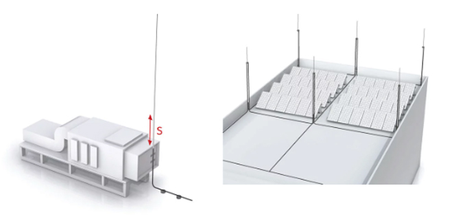
This system is ideal where space is in limited supply. Through using Insulated Lightning Conductor, the Air Terminal can be placed closer to the object to be protected – for example, roof-mounted plant or solar PV panels. Thus optimizing the lightning protection design
Used with objects where there is no possibility to maintain separation distance, due either to lack of sufficient space or simply for aesthetic reasons.
The cable simulates a separation distance of ≤0.75m in air and ≥1.5m in solid material and is used for maintaining the separation distance between the electrically conductive parts of the structure (to be protected) and the lightning protection system. Thus reducing flash over from the lightning protection system to exposed metallic and electrical structures – for example, air handling units, solar PV arrays, etc.

PROTECTIVE ANGLE
The protective area of the air terminal is determined by the rules
contained within BS:EN 62305 part 3 – “protective angle” method of
protection.

The minimum separation distance between the object being protected and the Lightning Protection System, is calculated according to the formulae for separation distances, given in BS:EN 62305 part 3.
The insulated cable does not have to replace the entire Lightning Protection down conductor, it can be connected to the conventional Lightning Protection System (Air Termination and Down Conductor network).
The insulated lightning conductor cable should be connected to the rest of the roof mesh (bare or PVC covered conductor) not less than 1.5m away from the object being protected.
The separation distance (where there is sufficient space to permit) can be increased by installing the Air Terminal on a free-standing mast and moving it further away from the object being protected. If 1m (in air) is required, move the mast 0.25m away (0.25m +0.75m simulated separation distance = 1.0m).
(The cable can also be run adjacent to conductive parts of the structure, as illustrated on the right.)
The cable should be connected to the rest of the roof mesh (bare or PVC covered conductor) not less than 1.5m away from the object being protected.
The separation distance (where there is sufficient space to permit) can be increased by installing the Air Terminal on a free-standing mast and moving it further away from the object being protected.
If 1m (in air) is required, move the mast 0.25m away (0.25m +0.75m simulated separation distance = 1.0m).
(The cable can also be run adjacent to conductive parts of the structure, as illustrated on the right.)
The cable has a tested arresting capacity of 100kA lightning surge current (1.2/50μs).
The cable is flexible and thus ideally suited for routeing in external or confined areas, roofs, walls or embedded in concrete. Bending radius of the cable is 280mm.

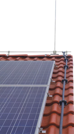
Pitched roof with PV arrays

NOTES ON MAXIMUM CONDUCTOR LENGTH
In cases where the separation distance required is greater than 0.75m, the use of additional cables is recommended to effectively reduce the separation distance. Such reduction (utilising additional cables) can only take place when the distance between the cables is not less than 0.2m. This distance (0.2m), minimises the interaction between the magnetic fields of the cables.
If however, the cables are run next to each other and less than 0.2m apart, the addition of an extra cable does not reduce either the separation distance or the maximum length of cable.
The values expressed in the table (right), are valid for all types of A and B electrodes, provided that the difference in resistance of an individual electrode is less than or equal to 2.
Should the installation require longer cables than indicated in the table, then we recommend that you contact us to provide detailed design advice and options.
